If you’re a keyway machining specialist like we are—someone who’s spent years troubleshooting cutters and alignments in our own shop—you know that even the most reliable keyway milling machine won’t turn out consistent, tight-tolerance slots without regular calibration. A lot of folks skip this step or wing it, using “good enough” measurements instead of following a structured process, and that’s where you get wobbly keys, misaligned shafts, and costly part rejections. As a supplier that’s built and serviced keyway milling machines for over a decade, we’ve calibrated hundreds of units for small job shops and large aerospace facilities alike, and we’ve put together this step-by-step guide that’s not just technical, but tested in real shop conditions. Keyway Milling
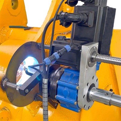
First, let’s clarify why calibration matters for keyway milling specifically. Unlike general milling machines, keyway work demands precision within 0.001 inches across the slot width, depth, and alignment to the workpiece’s centerline. Even a 0.002-inch shift in your cutter’s position can throw a key into a hub groove, cause premature bearing wear, or lead to parts failing during high-cycle operation. For us, when a customer brings in a machine that’s cutting inconsistent slots, 9 times out of 10, it’s a calibration issue—not a bad cutter or worn spindle.
Start with the pre-calibration prep work, because rushing this will derail every other step. You can’t calibrate a machine that’s not stable. First, turn the machine off and let it sit for at least 30 minutes if it’s been running hot—spindle expansion from heat is one of the most common hidden variables here. If you calibrate right after a long run, your measurements will be off by as much as 0.003 inches, and you’ll have to redo it. Next, check the machine’s base: keyway mills are often lightweight for small-batch work, so if the shop floor has any give (a common issue with concrete floors that haven’t been leveled in years), chock the machine feet with 0.25-inch hardened steel shims to eliminate deflection. We once had a customer complain their slots were 0.004 inches deeper on one side until we found their machine was sitting on a uneven concrete pad; shimming fixed the issue immediately.
Next, gather your tools—skip the cheap rulers or digital calipers here, you’ll need precision tools that meet ASME B46.1 standards. That means a dial indicator with a 0.0001-inch resolution (not a 0.001-inch model), a 1-inch calibration gauge block set, a parallel square, a test arbor that matches your standard end mill shank size (we use 1-inch and 1.25-inch arbors for most of our machines), and a machinist’s level accurate to 0.005 inches per foot. Also, clear the worktable of all debris—even a tiny metal shaving under a vise will throw off workpiece alignment, so vacuum the table and wipe it down with isopropyl alcohol before starting.
The first critical calibration step for keyway mills is aligning the spindle to the worktable’s T-slot centerline. This is where most new operators mess up, because they assume the factory alignment is still good. To do this: mount the test arbor in the spindle, set the dial indicator to read the arbor’s outer diameter, and zero the indicator at the arbor’s top. Then, slowly move the table (not the spindle) 180 degrees to the arbor’s bottom. If the indicator reading changes more than 0.001 inches, you need to adjust the spindle’s angular tilt. On most vertical keyway mills, this requires loosening the four spindle mounting bolts, tapping the spindle gently with a rubber mallet until the dial indicator returns a difference of less than 0.0005 inches, then retightening the bolts in a crisscross pattern to avoid shifting. We always stress using a rubber mallet here—steel hammers can chip the spindle’s finish and cause micro-wear over time.
Next, calibrate the table travel in the X and Y axes, which control the slot’s length and position. For keyway work, the slot must be parallel to the workpiece’s centerline, so table alignment is non-negotiable. Start with the Y-axis (the axis that moves the table forward and backward relative to the spindle): set the dial indicator on the table’s side, run the Y-axis 6 inches of travel, and check for any deviation. If the reading changes more than 0.0005 inches, adjust the Y-axis gib screws. The gib is the thin metal strip that eliminates play between the table and the machine’s bed; too tight and the table binds, too loose and it drifts during cuts. We recommend adjusting gibs until you can just slide a 0.002-inch feeler gauge between the gib and the bed, then check travel again. Repeat for the X-axis (left-right movement), which controls how offset the slot is from the workpiece’s edge. For end-mill keyway cuts, the X-axis alignment is what keeps the slot symmetric on the shaft—most customers use 1-inch diameter shafts, so we calibrate the X-axis to within 0.0003 inches for that standard size.
Then, calibrate the depth stop, which is the most frequently adjusted setting for keyway work, and the one that causes the most rejections if off. Depth is measured from the workpiece’s surface to the bottom of the slot, and for standard keyways like the 10mm standard (per ANSI B17.1), the depth must be exactly 5mm plus half the shaft diameter. To calibrate: mount a 0.5-inch diameter end mill (a common size for 1-inch shafts), set the depth stop to zero, then use the gauge block to test. The gauge block should sit on the workpiece’s height, so lower the spindle until the indicator reads zero on the block’s top. Then, set the desired keyway depth on the depth stop—if you need a 5mm depth for a 1-inch shaft, that’s 0.5 inches plus 0.025 inches, so set the stop to 0.525 inches. To test, mill a test slot in a piece of mild steel (same material you use for production parts), then measure the slot’s depth with a micrometer. If it’s 0.001 inches too deep, adjust the depth stop’s fine-tune screw 0.001 inches toward you; if too shallow, adjust it away. We do this three times in a row to confirm consistency—if each test slot is within 0.0005 inches, the depth stop is calibrated correctly.
Once you’ve got the basic axes aligned, you need to calibrate the quill travel, which is the part of the spindle that moves up and down to make the cut. Many operators forget that the quill can have lateral play, which causes the slot to be wider than the cutter. To check this: mount the dial indicator on the spindle, set the indicator to read the quill’s side, push the quill all the way in, then pull it out as far as it goes. If the indicator reading changes more than 0.0005 inches, adjust the quill’s lock nut or bearing adjustment. For our machines, we build in a pre-tensioned quill that eliminates this play, but after 5000 hours of use, the bearings will wear, so this adjustment is part of regular annual calibration.
After all individual calibrations, run a production-like test cut to confirm everything works. Use a standard 1-inch diameter shaft, mount it in a vise on the worktable, and mill a 1/8-inch wide keyway 1 inch long. Measure the slot’s width, depth, and alignment: the width should be within 0.001 inches of the cutter (so if you used a 0.125-inch end mill, the slot should be 0.124 to 0.126 inches), the depth within 0.001 inches of your target, and the slot’s center should be within 0.0005 inches of the shaft’s centerline. If this test passes, your machine is calibrated for production work. If not, go back and check the spindle alignment first—90% of test cut failures are caused by a misaligned spindle.
Now, as a keyway milling supplier, we know that calibration isn’t a one-time job. For high-production shops that run their machines 40+ hours a week, calibration should be done every 1000 hours of operation, or after every major tool change, spindle adjustment, or move of the machine. For small job shops that run less, twice a year is enough. We also offer pre-calibration checks for all the keyway mills we sell, so customers don’t have to guess if their machine is set up right when it arrives.

If you’re still struggling with calibration, or your keyway milling machine isn’t turning out the consistent parts you need, don’t hesitate to reach out to our team. We specialize in keyway milling equipment, from entry-level units for small shops to high-precision models for aerospace and automotive work, and we can help you troubleshoot alignment issues, provide replacement parts, or offer custom calibration services for your specific operations. Whether you’re just setting up your first keyway mill or looking to upgrade your existing equipment, we’re here to make sure your cuts are tight, your parts are consistent, and your downtime is minimal.
Line Boring Bar References
- Machinists’ Handbook, Vol. 3: Milling, ASME International, 2018.
- ANSI B17.1-2019, Keyways and Key Seats for Metric Keys, American National Standards Institute, 2019.
- Machine Tool Calibration Guidelines, National Institute of Standards and Technology (NIST), 2021.
- Keyway Milling Best Practices, Modern Machine Shop, 2020.
Shangqiu JDA Machinery Technology Co., Ltd.
With abundant experience, we are one of the most professional keyway milling manufacturers and suppliers in China. We warmly welcome you to buy cheap keyway milling for sale here from our factory. Quality products and reasonable price are available.
Address: No. 55 Pingyuan Middle Road, Liangyuan District, Shangqiu, Henan, China
E-mail: sales@jdamachines.com
WebSite: https://www.jdamachines.com/
